
Vector vs Raster for Metal Tooling: How to Format Your AI and EPS Files for 3D Relief
A beautifully shaded bird can look three-dimensional on a screen. That does not tell the toolmaker how far its wing should rise above the background.
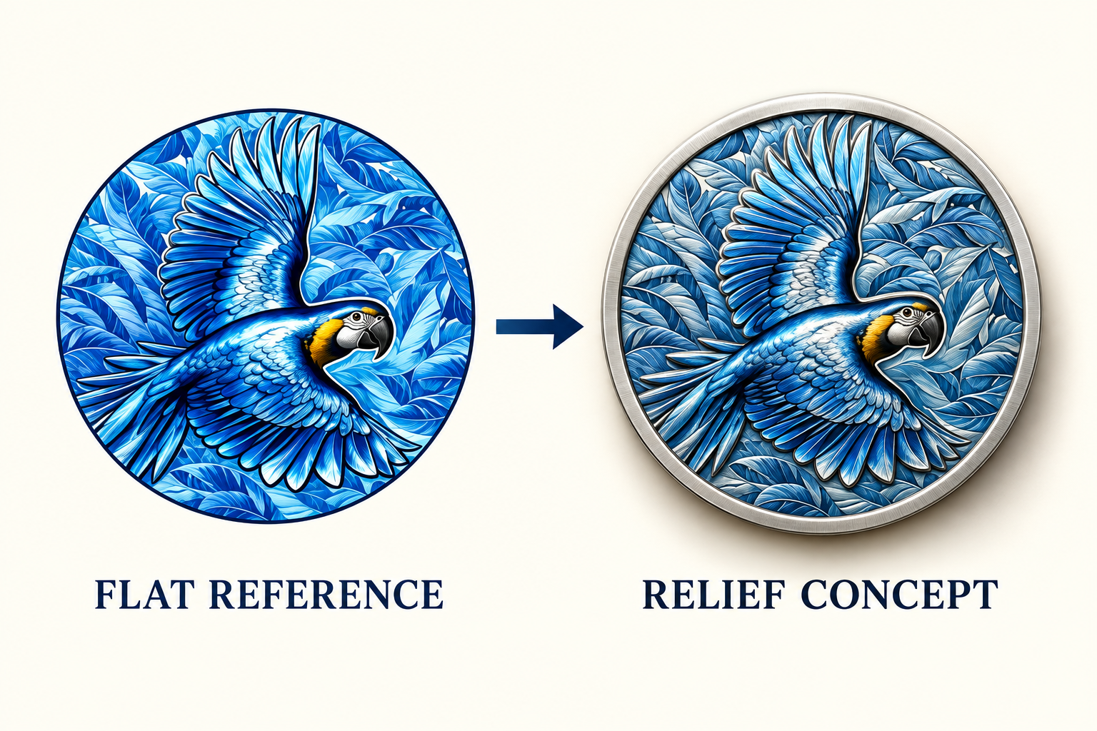
The missing dimension is a decision
Imagine ordering a bird-themed commemorative coin. Your illustration shows a wing crossing a leafy background. A dark patch could mean a shadow, a blue feather or a recessed surface. The image looks convincing, but those interpretations would produce different objects.
This is the central difference between an attractive reference and a manufacturing definition. The first describes an appearance. The second must establish geometry, dimensions and how the design will be made.
You do not need to become a CNC programmer to commission relief. You do need to explain the important forms and approve how the factory interprets them.
Pixels describe appearance
JPG and PNG references communicate texture, color and visual character.
Paths describe outlines
Editable curves help define borders, lettering and separate design regions.
Surfaces describe depth
Modeled geometry establishes height, transitions and sculpted form.
An AI file is not automatically a 3D file
Here, AI means the Adobe Illustrator file format. AI and EPS files can contain useful vector artwork, but the extension alone does not prove that the drawing consists of editable paths. A placed photograph remains a raster image inside its container.
Adobe’s raster and vector comparison explains the distinction. A clean vector outline can be resized and edited without tracing a pixel edge. It still does not say whether the bird’s breast should be rounded, flat or recessed.
Likewise, a JPG is not useless. It can be a valuable modeling reference. The practical question is what interpretation, tracing or sculpting is needed before it becomes suitable manufacturing data.
Give the bird a hierarchy
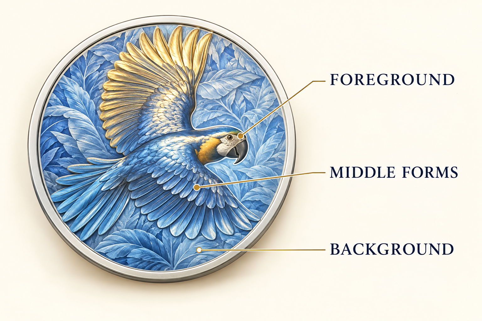
Start with three descriptive levels: foreground, middle and background. In our concept, the head and main wing might command attention, overlapping feathers form the middle, and foliage stays quieter behind them.
These are instructions about visual priority, not measured heights. The modeler still needs to resolve the transitions between forms. A feather should not become a stack of disconnected shelves simply because the brief used three labels.
Mark the details that must survive: the beak profile, eye position and direction of flight, for example. Then identify textures that may be simplified. At coin size, a clear silhouette often contributes more than a forest of tiny grooves.
Organize the artwork like a small project folder
Use descriptive layer names instead of leaving the supplier to inspect dozens of unnamed groups. Keep a native editable copy, and include a PDF or image preview showing the intended appearance. Confirm which exchange formats the supplier can use.
In the production copy, convert lettering to outlines while retaining your editable original. Include linked references, remove accidental duplicate paths and make the finished dimensions explicit. Separate a genuine cut-out from an area that merely looks dark.
Suggested file structure
Five layers. Fewer guesses.
This is an organizational example, not a universal CAD import standard.
- 01_OUTLINE — outer shape and overall size.
- 02_RELIEF — main forms and overlap notes.
- 03_TEXT — lettering and its location.
- 04_COLOR_FINISH — filled, printed and exposed metal areas.
- 05_NOTES — reverse, orientation, dimensions and references.
Why “make it deeper” is not enough
A deeper sculpt can alter the relationship between the rim, lettering and central subject. It may also affect how the selected manufacturing process reproduces and releases the shape. More depth is a design change, not a universal upgrade.
Ask for a front view and an oblique or side view of the proposed relief. Discuss any narrow recesses, steep transitions or overhanging-looking details. Tool access and process constraints need to be reviewed by the supplier; a dramatic render cannot establish that they are acceptable.
For the broader style decision, compare 2D and 3D medal relief. Keep color approval separate from geometry approval so a beautiful finish does not distract from the shape.
These are related deliverables, but they are not interchangeable files.
What happens between the model and the machine?
In a CNC workflow, manufacturing preparation follows the geometry. Autodesk’s Manufacture overview separates creating a design, setting up manufacturing and programming toolpaths. Sending an illustration does not replace those steps.
The factory may need to rebuild surfaces, prepare the tooling geometry and check the machining approach. Ask which artwork or modeling charges are included, how revisions are handled and what you will receive for approval. Do not assume an illustration fee includes ownership or delivery of every engineering file.
Send a brief the modeler can act on
Try: “Please develop this bird into a circular relief. Keep the head and leading wing prominent, place foliage behind them, and preserve the outer silhouette. Confirm the proposed size, thickness and process before tooling. Send front and angled views for approval.”
Add quantity, reverse design, finish and the reference files you are authorized to use. If a feature is important, annotate it directly rather than relying on a long email description.
Approve the geometry deliberately, and discuss a physical sample for critical details. The best handoff is not the most complicated file. It is the one that makes the important decisions visible.
Have artwork but no relief model?
Send Extra Dream your reference, intended size and quantity. We can discuss the modeling scope and the decisions needed before tooling.
Discuss your relief project ↗